
What Is a Roof Framing Plan? How to Read One Like a Pro

A roof framing plan is the drawing that tells you how a roof is structurally assembled. It is less about how the roof looks from the street and more about what is supporting that shape: rafters, trusses, ridge members, hips, valleys, joists, beams, and the load-bearing points that carry everything down into the walls and foundation.
For homeowners, that matters when you are trying to understand whether a remodel is realistic. For architects, it is the sheet that keeps the roof geometry aligned with the structural intent. For builders, it is where the actual framing logic begins to show up.
In practice, a roof framing plan helps answer questions like: Is this roof stick-framed or trussed? Where are the bearing points? Which members are structural, and which are just layout references? Does the roof shape in the design actually match the way it will be built?
If you are comparing drawings, one useful companion resource is how to read a residential roof plan drawing, which focuses more on roof geometry, slopes, and plan-view roof layout. This article goes deeper into the structural side.
What a Roof Framing Plan Is and Why It Matters
A roof framing plan is a plan-view drawing that shows the roof’s structural framework. In a typical set of construction documents, it may appear in the structural sheets, the architectural sheets, or both, depending on how the project is organized.
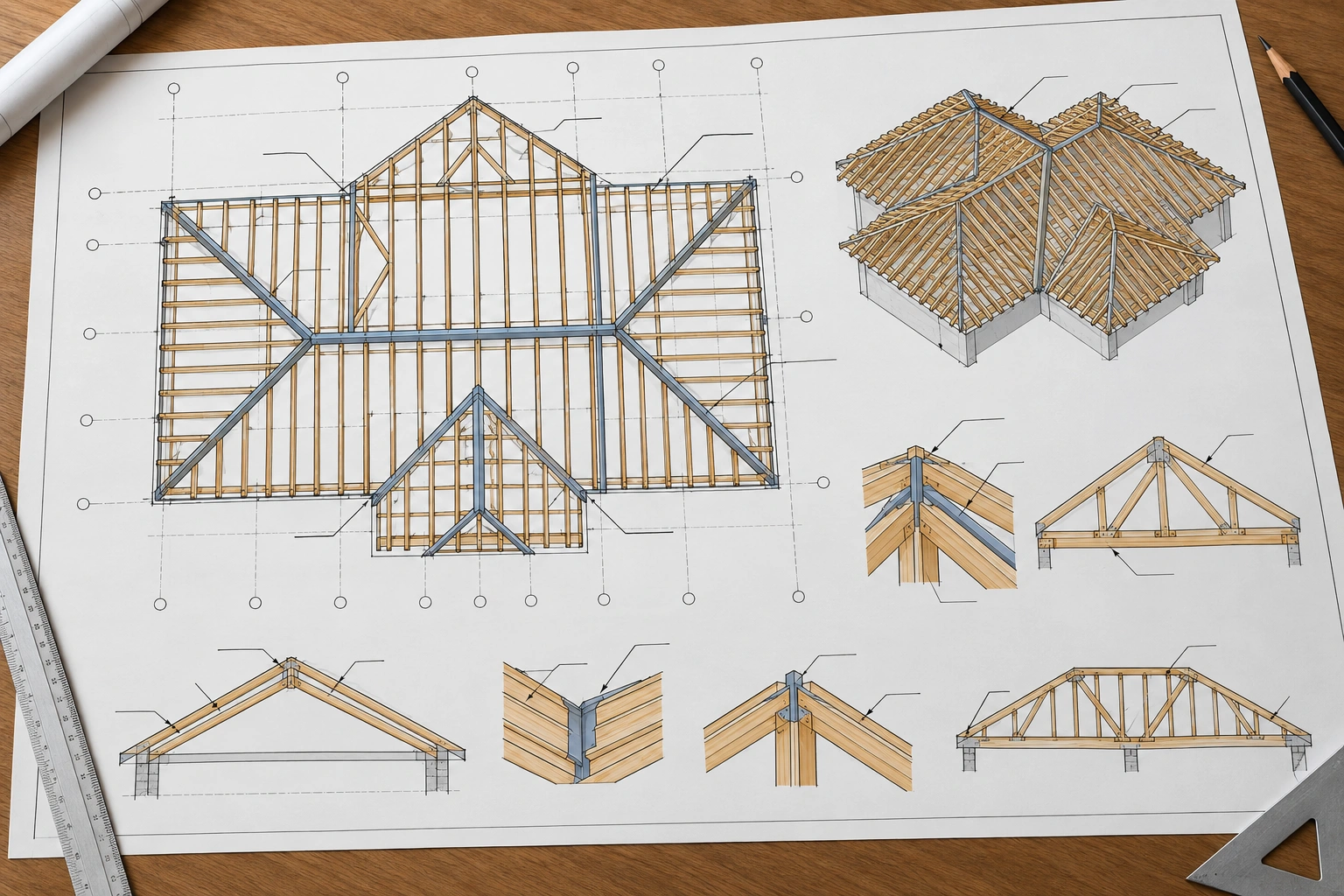
The key value of the drawing is that it turns a roof from an abstract shape into a buildable system. You can usually see how the roof is divided into framed sections, where major members land, and how the roof connects to the supporting structure below. That helps with:
- structural coordination
- estimating framing complexity
- checking whether the roof form is buildable
- identifying where engineering review may be needed
- coordinating roof openings, penetrations, and transitions
A simple gable roof may need only a straightforward framing layout. A roof with hips, valleys, dormers, or multiple slopes often needs much more information to avoid conflicts on site.
The drawing does not replace structural judgment. It is a communication tool. If the plan is unclear, incomplete, or inconsistent with the elevations and sections, that is a warning sign, not a detail to “figure out later.”
Roof Framing Plan vs. Roof Plan vs. Structural Drawings
These terms get mixed up constantly, but they do different jobs.
| Document | What it mainly shows | Why it matters |
|---|---|---|
| Roof plan | Roof shape, perimeter, ridges, hips, valleys, slopes, and openings | Helps you understand the roof geometry and drainage direction |
| Roof framing plan | Structural framing layout: rafters, trusses, beams, bearing points, and framing direction | Tells you how the roof is built and supported |
| Structural drawings | Broader structural system: foundations, walls, beams, connections, framing notes, and details | Provides the engineering and construction logic behind the building |
A roof plan can show the outline of the roof and major features, but it may not tell you exactly how the roof is framed. A roof framing plan fills in that structural layer. Structural drawings go wider than the roof and may include the whole load path from roof to foundation.
That distinction matters on remodels. A roof plan might show a new opening or slope change, but the roof framing plan is where you see whether that change is actually supported.
Start Here: How to Read the Drawing in the Right Order
The fastest way to get lost is to jump straight to the lines. Read the sheet in this order instead.
1) Check the title block and sheet number
The title block tells you what kind of drawing you are looking at, which discipline issued it, and whether it is a current revision. If the sheet number references structural details or sections elsewhere in the set, make note of that immediately.
2) Find the scale and orientation
Not every roof framing plan is drawn at the same scale. The scale helps you judge whether a member layout is detailed enough for construction or only intended as a general reference.
3) Locate the structural grid, if present
Many projects use numbered and lettered grid lines to locate the roof framing relative to the building. That grid is especially useful on larger buildings or additions where multiple roof planes overlap.
4) Read the roof outline and major members
Look for ridges, hips, valleys, beams, trusses, and bearing lines. These are the pieces that tell you how the roof is organized.
5) Review notes, tags, and callouts
A roof framing plan often relies on notes and references to explain member sizes, connection requirements, or special conditions. The plan may not show every detail directly; instead, it points you to another sheet.
6) Cross-check with sections and elevations
Roof height and construction details are often clarified in sections, elevations, or enlarged details rather than on the framing plan alone. In other words, the framing plan usually works together with other sheets to show both geometry and construction intent. See the referenced roof framing tutorial at VDCI’s structural drawing guide and the source video How to read Roof and Roof framing Plan.
How to Identify Roof Members on the Plan
The roof framing plan is easier to read once you know what the major members usually represent.
Rafters
Rafters are the sloped framing members that run from the ridge area down to the exterior walls or supporting beams. In stick framing, they are often the primary roof structure. On a plan, they may appear as repeated parallel lines or as labeled framing members with spacing notes. For example, you might see notes like 2×8 RAFTERS @ 16″ O.C. or a repeated line pattern showing the rafter direction.
Trusses
Trusses are engineered assemblies that span between supports and arrive on site as predesigned units. On the plan, they are often tagged by type or number rather than drawn as every individual piece. A plan may show labels such as T1, T2, or TRUSS 5, along with spacing notes like @ 24″ O.C. If the roof uses trusses, the plan may be more about layout and bearing than about field cutting.
Ridge beam vs. ridge board
This is one of the most important distinctions in roof framing.
A ridge board is generally a non-structural alignment member used to help rafters meet at the ridge. A ridge beam is structural and carries load. If a plan shows a ridge beam, that usually changes the support logic below it, because the beam must transfer load to posts or walls designed to carry it. A label such as RB or RIDGE BEAM usually signals that the ridge is doing structural work.
Hip rafters
Hip rafters run diagonally where two roof planes meet at an external corner. They are common in hip roofs and make the framing more complex than a simple gable roof. On drawings, they are often shown as diagonal members running from the ridge to the outside corner, sometimes tagged HIP RAFTER or HR.
Valley rafters
Valley rafters occur where two roof planes intersect and direct water and framing loads into a common line. They are especially important around dormers, additions, and intersecting roof forms. On a plan, they are usually drawn as diagonal lines cutting into the roof intersection and may be labeled VALLEY or VR.
Purlins
Purlins are horizontal members used in some roof systems to support rafters or roof covering loads, depending on the framing approach. Their role is project-specific, so the plan and details should be read together. They may appear as short members crossing or supporting rafters, with labels such as PURLIN or a size note.
Ceiling joists
Ceiling joists tie the building together below the roof and may help resist outward thrust in certain framing systems. They are not always shown the same way on every plan, so check the structural notes and related framing sheets. You may see labels like CJ or CEILING JOISTS @ 16″ O.C.
If you are still sorting out the core framing system, the companion article on trusses vs. rafters is useful because the plan reads very differently depending on which system is used.
Symbols, Line Types, Abbreviations, and Labels
There is no single universal symbol set that every office uses in exactly the same way, so treat the legend and notes as authoritative for that project. Still, most roof framing plans use a recognizable visual language.
What to look for
- Solid lines often show visible or primary framing edges
- Dashed lines may indicate hidden elements, overhead members, or framing below/above the plan cut
- Arrows may show slope, direction of fall, or framing direction
- Tags or bubbles may identify truss types, member marks, or detail references
- Abbreviations may indicate member size, spacing, or material type
How to decode a specific sheet
Start with the legend, if one is provided, because it defines the office’s symbols and line conventions. Then check the general notes for member sizes, spacing, and any special framing rules. After that, follow callouts and detail references to the enlarged drawings that explain conditions the plan cannot show fully.
For example, a roof framing plan might show:
– T-1, T-2, or TRUSS A for truss types
– 2×10 @ 16″ O.C. for rafter or joist spacing
– RB for ridge beam
– (2) 1-3/4″ x 9-1/4″ LVL for a built-up beam
– S1, D4, or similar bubbles pointing to a structural detail
Common reading rule
If a line or label is doing structural work, do not assume it is decorative. A diagonal line might be a hip rafter, or it might be a slope indicator. A tag might refer to a truss package, or it might point to a detail that contains the actual member sizing.
That is why notes matter. A clean-looking plan can still be incomplete if it does not identify sizes, spans, or support conditions.
Reading Dimensions, Span, Pitch, and Spacing Notes
The numbers on a roof framing plan are not just drafting clutter. They are what make the roof buildable.
Span
Span tells you how far a member is expected to reach between supports. If a member spans too far for the intended system, the plan may require a beam, a bearing wall, or an engineered solution.
Pitch or slope
Roof pitch shows steepness. It affects framing geometry, drainage behavior, and how the roof planes meet at ridges, hips, and valleys. A low-slope roof and a steep roof may use different framing logic even if the footprint is similar.
Spacing
Spacing notes tell you how far apart the rafters or trusses are placed. That spacing affects layout, material takeoff, and coordination with sheathing and ceiling systems.
Bearing dimensions
Look for notes that show where framing bears on walls, beams, or posts. If the plan is vague here, do not assume the roof can simply sit anywhere on the wall line.
Why this matters in real projects
A homeowner may see a roof change on a remodel and assume it is only a design issue. In reality, a small change in pitch or span can alter the structural system. A builder estimating materials also needs these numbers to know whether the roof is conventional framing or a more customized assembly.
Understanding Load Paths and Support Requirements
A roof is not just sitting on top of the house. Its weight, and the loads acting on it, need a path down through the structure. That path is the load path.
For a basic roof, the load may travel from rafters or trusses into bearing walls, then down through the wall framing into the foundation. If the roof includes a ridge beam, posts, or concentrated loads, the support system becomes more specific.
This is where the framing plan is especially important. It shows where the roof expects support, and it can reveal whether a wall is structural or merely a partition. If a plan suggests removing or relocating a wall beneath a ridge beam or major bearing line, that is not a casual design tweak. It is an engineering question.
For general building-envelope coordination, the U.S. Department of Energy’s Building America guidance is a useful reference point for how building assemblies work together as systems. Roof framing is part of that larger system.
How to Use Section Callouts and Detail References
Roof framing plans often point to other sheets instead of spelling everything out in one place. That is normal.
A section callout may show where to find a cut through the roof or wall. A detail reference may point to a larger drawing of a connection, beam seat, valley condition, or framing intersection. If the roof framing plan says “see detail,” follow it.
This is especially important where roof planes intersect, where there are changes in height, or where the framing transitions over an addition. Those are the spots where plans often compress the most information into the fewest lines.
A practical rule: if you cannot explain how the load transfers at a transition, you probably have not read far enough into the drawing set.
Stick-Framed Roofs vs. Truss Roofs
The framing system changes what the plan needs to show.
Stick-framed roofs
Stick framing uses individual rafters and related members built on site. It can offer more flexibility for unusual roof shapes, additions, and adjustments in the field. The trade-off is that it usually requires more layout judgment and coordination during construction.
Truss roofs
Truss roofs use preengineered assemblies. They can simplify the on-site framing process because the truss geometry is manufactured ahead of time. The trade-off is less flexibility. Field modifications to trusses are not something to improvise; if a truss needs to change, it generally requires approved engineering.
How this affects the plan
A stick-framed roof plan may show more member logic, bearing, and layout relationships. A truss layout may show truss marks, spacing, and support points instead. If you read a truss layout as if it were a rafter layout, you can miss the actual structural intent.
Roof Openings and Penetrations: What to Check
Roof framing plans should also be read with roof openings in mind. Skylights, chimneys, roof hatches, vents, and mechanical penetrations can all affect framing layout and support.
Look for:
– opening dimensions
– framing around the opening
– headers or trimmer members
– notes about coordination with mechanical or plumbing trades
– detail references for curb or flashing conditions
If an opening interrupts rafters, trusses, or a valley condition, the plan should show how that interruption is framed. If it does not, the coordination may be incomplete.
What to Check Before Building or Reviewing the Plan
Before anyone starts framing from the drawing, verify these points:
- The roof shape matches the architectural plan and elevations
- The framing system is clearly identified as stick-framed or trussed
- Bearing points are shown and coordinated with the floor and wall plans
- Roof pitch and slope match the intended roof form
- Member tags, sizes, and spacing are consistent across sheets
- Detail references are followed for intersections and transitions
- Revision marks have been reviewed so you are not using an outdated sheet
- Any opening, dormer, or roof cutout has a structural note attached to it
That checklist is especially useful on remodels, where the existing structure may not match the new design assumptions.
Common Mistakes and Red Flags
A few errors show up again and again.
Mistaking a roof plan for a framing plan
A roof plan can tell you the roof shape without telling you how it is supported. That is a dangerous gap if you are making structural decisions.
Assuming every line means a rafter
Some lines show slopes, edges, or hidden conditions rather than framing members. Read the legend and notes before assigning meaning.
Missing a ridge beam requirement
A ridge board and a ridge beam are not interchangeable. If the design depends on a structural ridge, the support below it matters.
Ignoring revision clouds
The latest revision may change bearing, spacing, or member type. Old plans are one of the easiest ways to create avoidable field problems.
Treating a drawing as approval
A drawing is not a substitute for professional review when the roof is new, altered, or structurally uncertain.
For storm and envelope context, the Insurance Institute for Business & Home Safety has useful educational material on how roof systems behave under severe conditions at IBHS. That does not replace project-specific design, but it reinforces why roof structure should be read carefully, not casually.
When to Consult an Architect, Structural Engineer, or Qualified Builder
Bring in an architect, structural engineer, or qualified builder when any of the following apply:
- the roof shape is changing
- a load-bearing wall may be removed or moved
- the plan shows a ridge beam, large span, or unusual support condition
- the roof uses multiple intersecting planes with valleys and hips
- the framing system is unclear or the sheets conflict
- trusses are being modified
- the roof opening, dormer, or addition affects the existing load path
A homeowner can often understand the basics of the plan, but structural decisions should be verified by a licensed professional when the design changes the building’s load path. That is not overcautious; it is how you avoid turning a drafting issue into a structural one.
FAQ: Roof Framing Plan Basics
What is included in a roof framing plan?
Usually the structural layout of the roof: rafters, trusses, beams, hips, valleys, bearing points, notes, and references to related details.
Can I read one without being a draftsman?
Yes, at a basic level. Focus on the title block, roof outline, major members, notes, and detail callouts before trying to interpret every line.
Is a roof framing plan the same as a roof plan?
No. A roof plan is mainly about shape and roof geometry. A roof framing plan is about how the roof is structurally built.
Do all roof framing plans show the same symbols?
No. Symbols and abbreviations can vary by project and office standard, so always use the legend and notes on the actual set.
What do common member tags look like?
They often appear as short labels such as T1, RB, HR, VR, or spacing notes like 2×8 @ 16″ O.C. Always read the tag with the legend and nearby callouts.
Do I need an engineer to approve it?
If the roof is new, altered, or structurally unclear, yes, the design should be reviewed by a licensed professional before construction.
What is the biggest thing to verify?
The load path. If you know where the roof load goes and what supports it, you understand the most important part of the drawing.
How does this relate to the real roof on site?
The plan is the map; the framing is the built result. If the plan and the other drawings do not coordinate, the field crew is left to solve a structural problem that should have been resolved on paper.